|
| |
TM 10-4930-250-13&P
fueltransferpump.Thesuctionsideof thepumpis suppliedbynon-collapsiblehosesconnectedin parallelto theoutletside
of the fuel drums. Purnpage from the discharge side of the pump moves through the liquid fuel filter-separator to the fueling
points. Fueling is accomplished at four fueling points, using any combination of D 1, CCR or GFA nozzles. Fuel
recirculation occurs continually during system operation.
The fuel transfer pump is a centrifugal pump with an impeller to move the pumpage. A positive displacement, rotary vane
pump on the same shaft serves as a priming pump for the main impeller, allowing the pump to be started with a dry system.
Fuel is drawn from the fuel drums through suction hoses into a three-way pump inlet manifold. The impeller rotation induces
a swirling motion in the fuel in the body of the manifold which, if not corrected, would cause the pump to cavitate. To
correct this situation, three equally spaced fins in die manifold outlet straighten the flow, reducing pump cavitation and
increasing efficiency. The inlet manifold empties directly into the main impeller cavity of the fuel transfer pump which
discharges the purnpage through a discharge housing to the liquid fuel filter-separator. A flapper-type check valve in the
discharge housing prevents the flow of fuel back into the fuel transfer pump, enabling the integral vane pump to move fuel.
The liquid fuel filter-separator houses a horizontal filtration vessel containing three coalescer elements to remove particles
from the pumpage and coalesce trapped water, and a separator to remove the water drops from the purnpage. The fuel flows
through the separator to a recirculation manifold.
The recirculation manifold provides three outlet ports. A three-inch outlet passes pumpage to a three-inch, fifty-foot
discharge hose and on to the delivery hoses and nozzles. Two-inch outlets are provided for recirculation of a portion of the
purnpage. One of the two-inch outlets (figure 1-17, RECIRC 2) allows full flow recirculation; the other two-inch outlet
(figure 1-17, RECIRC 1) has a reduced bore to limit recirculation to five gpm.
The pumping subsystem design incorporates a recirculation capability to continuously filter the pumpage, and maintain
pumpage pressure and temperature within safe limits for continuous operation. The system provides three modes of
recirculation: RECIRC 1 from the recirculation manifold limits recirculation to five gpm (normal fueling operation),
RECIRC 2 allows full flow recirculation from the recirculation manifold; and RECIRC 3 provides the capability for full
recirculation from a D1 nozzle, a CCR nozzle or both through a nozzle recirculation wye fitting. Each mode routes the
pumpage through two-inch hoses and a cross-wye fitting assembly to the fuel drum inlets, figure 1-16.
1.11.2
Power Subsystem.
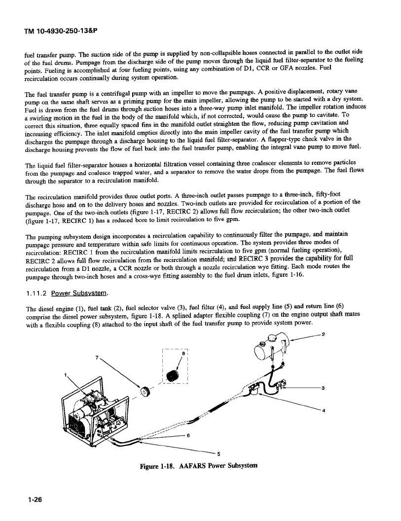
The diesel engine (1), fuel tank (2), fuel selector valve (3), fuel filter (4), and fuel supply line (5) and return line (6)
comprise the diesel power subsystem, figure 1-18. A splined adapter flexible coupling (7) on the engine output shaft mates
with a flexible coupling (8) attached to the input shaft of the fuel transfer pump to provide system power.
2
7
[----
8
-3
4
44
5
Figure
1-18.
AAFARS
Power
Subsystem
1-26
|