Order this information in Print

Order this information on CD-ROM

Download in PDF Format


Click here to make tpub.com your Home Page

Page Title: Figure 4-13. Auxiliary Pump Rotor Vane Replacement
Back | Up | Next

Click here for a printable version

Google


Web
www.tpub.com

Home


Information Categories
.... Administration
Advancement
Aerographer
Automotive
Aviation
Combat
Construction
Diving
Draftsman
Engineering
Electronics
Food and Cooking
Math
Medical
Music
Nuclear Fundamentals
Photography
Religion
USMC
   
Products
  Educational CD-ROM's
Printed Manuals
Downloadable Books


TM 10-4930-250-13&P 
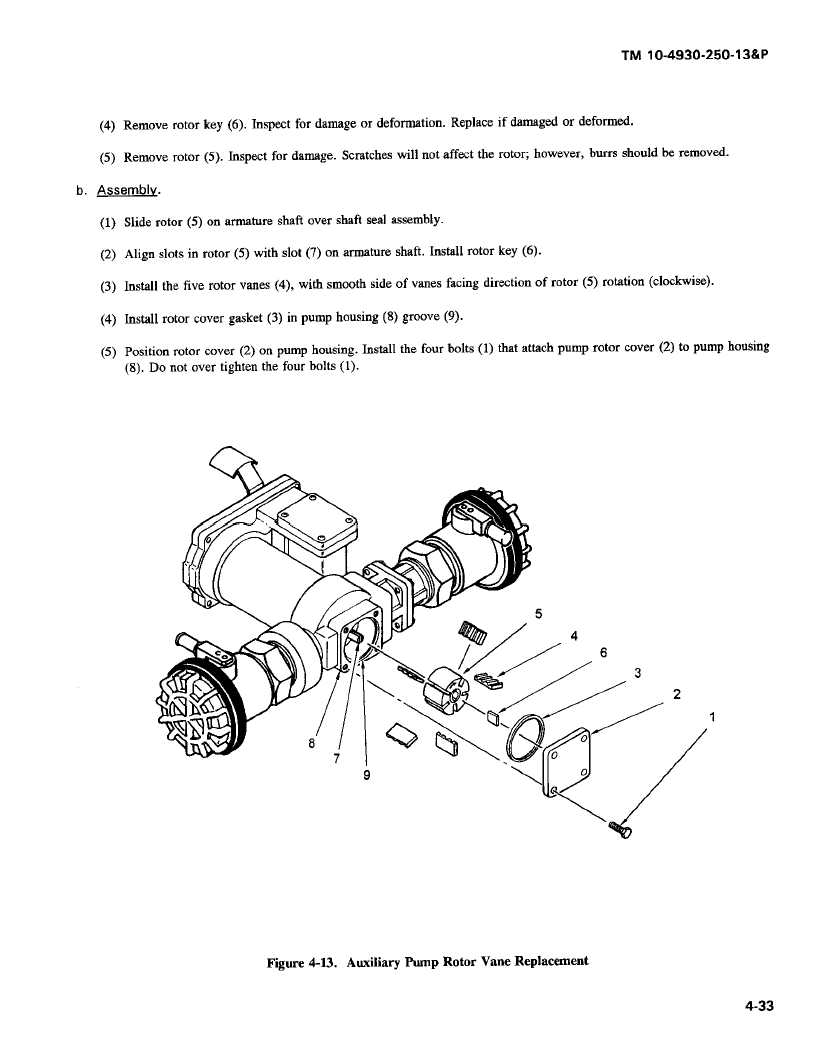
(4)  Removerotorkey (6). Inspectfor damageordeformation.Replaceif  damagedor deformed. (5)   Remove  rotor  (5).  Inspect  for  damage. Scratches will  not  affect the rotor;   however,  buffs  should be removed. b.   Assembly. (1) Slide  rotor   (5)  on armature   shaft  over  shaft  sea] assembly. (2) Align   slots in  rotor  (5) with   slot (7)  on armature  shaft. Install  rotor  key  (6). (3) Install   the five  rotor  vanes (4),  with  smooth  side of vanes facing  direction  of  rotor  (5)  rotation  (clockwise). (4) Install  rotor  cover  gasket (3)  in  pump housing (8)  groove (9). (5) Position  rotor  cover  (2) on  pump housing.  Install  the four bolts  (1)  that attach pump rotor  cover  (2) to pump housing (8).  Do  not  over tighten the four  bolts  (1). 5 4 6 3 2 8 0 1 7 0 9 0 Figure 4-13. Auxiliary Pump Rotor Vane Replacement 4-33

Privacy Statement - Press Release - Copyright Information. - Contact Us - Support Integrated Publishing

Integrated Publishing, Inc. - A (SDVOSB) Service Disabled Veteran Owned Small Business