Order this information in Print

Order this information on CD-ROM

Download in PDF Format


Click here to make tpub.com your Home Page

Page Title: Figure 4-11. Auxiliary Pump Module
Back | Up | Next

Click here for a printable version

Google


Web
www.tpub.com

Home


Information Categories
.... Administration
Advancement
Aerographer
Automotive
Aviation
Combat
Construction
Diving
Draftsman
Engineering
Electronics
Food and Cooking
Math
Medical
Music
Nuclear Fundamentals
Photography
Religion
USMC
   
Products
  Educational CD-ROM's
Printed Manuals
Downloadable Books


TM  10-4930-250-13&P (4) 
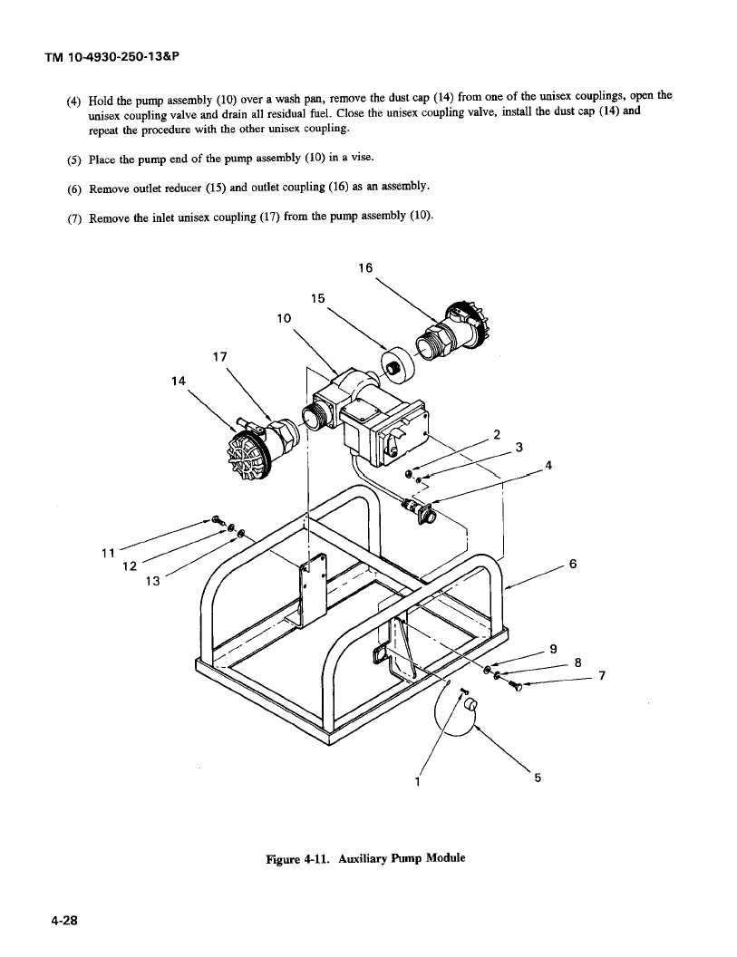
Hold  the  pump  assembly  (10)  over  a wash  pan,  remove  the  dust  cap (14)  from  one of  the  unisex  couplings,   open the unisex  coupling  valve   and drain   all  residual  fuel.  Close the  unisex  coupling  valve,  install   the  dust  cap (14)  and repeat  the  procedure   with   the  other  unisex  coupling. (5) Place  the pump  end  of  the pump   assembly  (10)  in  a vise. (6) Remove  outlet  reducer  (15)  and outlet  coupling  (16)  as an assembly. (7) Remove  the  inlet  unisex  coupling   (17)  from  the pump  assembly (10). 16 15 10 17 14 2 3 4 12 6 13 9 8 7 1 5 Figure   4-11.   Auxiliary    Pump  Module 4-28

Privacy Statement - Press Release - Copyright Information. - Contact Us - Support Integrated Publishing

Integrated Publishing, Inc. - A (SDVOSB) Service Disabled Veteran Owned Small Business