|
| |
TM 10-4930-246-13&P
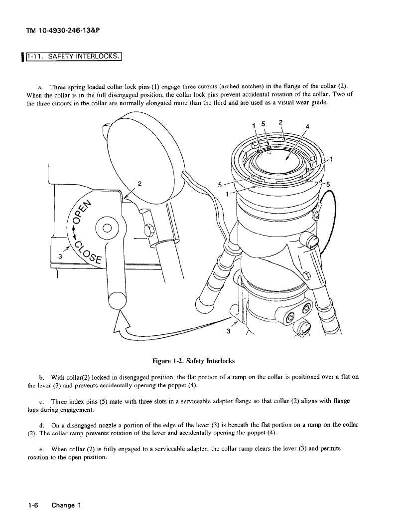
a. Three spring loaded collar lock pins (1) engage three cutouts (arched notches) in the flange of the collar (2).
When the collar is in the full disengaged position, the collar lock pins prevent accidental rotation of the collar. Two of
the three cutouts in the collar are normally elongated more than the third and are used as a visual wear guide.
5
2
4
2
5
-5
3
Figure 1-2. Safety Interlocks
b. With collar(2) locked in disengaged position, the flat portion of a ramp on the collar is positioned over a flat on
the lever (3) and prevents accidentally opening the poppet (4).
c.
Three index pins (5) mate with three slots in a serviceable adapter flange so that collar (2) aligns with flange
lugs during engagement.
d.
On a disengaged nozzle a portion of the edge of the lever (3) is beneath the flat portion on a ramp on the collar
(2). The collar ramp prevents rotation of the lever and accidentally opening the poppet (4).
e.
When collar (2) is fully engaged to a serviceable adapter, the collar ramp clears the lever (3) and permits
rotation to the open position.
1-6
Change 1
|