|
| |
TM 10-4930-242-13&P
1-8. LOCATION AND DESCRIPTION OF MAJOR COMPONENTS.
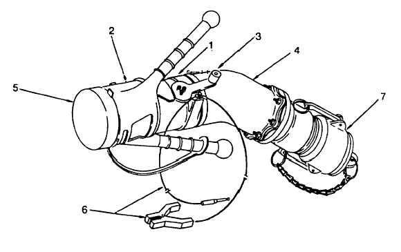
Major components of the D- 1 pressure fueling nozzle are shown in figure 1-1.
Figure 1-1. D-1 Pressure Fueling Nozzle Major Components
a.
Nozzle Body. The nozzle body (1) contains the poppet assembly and fuel strainer.
b.
Nozzle Collar. The nozzle collar (2) mates with the aircraft receptacle The bumper on face of collar and the
internal slots allow positioning of the nozzle before poppet valve can be opened.
c.
Handle Assembly. The handle assembly (3) allows the poppet valve assembly to be opened and closed.
d.
Elbow. Swivel. The swivel elbow (4) rotates with the nozzle engaged allowing the hose to be positioned free of
kinks or twists.
e.
Cover A cover (5) is furnished to cover the nozzle outlet when not connected to a system for servicing.
f.
Ground Cable. A ground cable (6) is provided for grounding the nozzle to the aircraft prior to connection A
ground plug is provided for inserting into the aircraft ground receptacle, a clip type ground is used where a
ground plug receptacle is not available.
g.
Coupling Assembly. The coupling assembly (7) allows the nozzle assembly to be connected and disconnected
from a fuel serving source.
1-3
|