|
| |
TM 10-4930-240-13
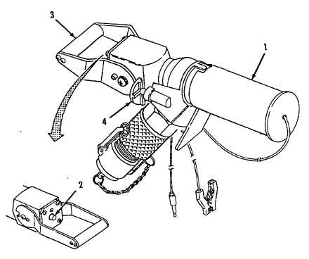
2-3. CLOSED CIRCUIT REFUELING (CCR) NOZZLE CONTROLS.
Refer to figure 2-3.
Quick-Disconnect Automatic Shutoff Coupler Collar (1).
Connects nozzle to aircraft refueling adapter. Pull back spring loaded collar to disconnect nozzle. Collar
automatically moves forward to lock nozzle in place.
Flow Indicator (2).
Red indicator extends from back of nozzle body when fuel flow through the nozzle has stopped or handle
has been moved to CLOSE position.
Handle (3).
Starts and stops fuel flow through the nozzle. The handle is held m the CLOSE position by a spring loaded
latch (4) Depress latch and raise handle to OPEN position to allow fuel flow. Pull handle down to CLOSE
position to stop fuel flow.
Latch (4).
Holds handle (3) in the CLOSE Position. Depress latch to release handle (3).
Refer to TM 10-4930-243-13&P for additional information, description and use of the operator's controls and
indicators on the CCR Nozzle.
Figure 2-3. CCR Nozzle Controls and Indicators.
2-5
|