|
| |
TM 10-4930-240-13
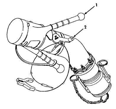
2-1. SINGLE POINT RFUELING NOZZLE (D1) CONTROLS.
Refer to figure 2-1.
Locking Handles (1).
Two locking handles on the nozzle body aid positioning and connection of the nozzle to the aircraft refueling
adapter. The handles are turned to the right to connect the nozzle; left to disconnect.
Control Lever (2).
The control lever has two positions, OPEN and CLOSE. When the nozzle is connected to the aircraft
refueling adapter, rotating the crank handle to OPEN allows fuel flow through the nozzle. When set to
CLOSE, fuel flow is stopped. Mechanical locks prevent setting the crank handle to OPEN when the nozzle
is not connected or disconnecting the nozzle before the lever is set to CLOSE.
Refer to TM 10-4930-242-13&P for additional information, description and use of the operator's controls and
indicators on the D1 Nozzle.
Figure 2-1. Single Point Refueling Nozzle (D1) Controls.
2-3
|