|
| |
TM 10-4930-238-12&P
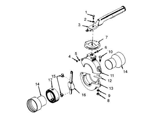
Figure 4-9. Butterfly Valve Assembly, Disassembly/Reassembly.
f. Reassembly.
(1)
Refer to Figure 4-9 and install seat (17) on disc shaft (16) and install bearing (15) in lower body.
(2)
Install assembled disc shaft (16) and seat (17) in lower body half (13) and install in lower body.
(3)
Install other bearing (15) and two pipe ends (14) in upper body half (11) and position upper body
half (11) on lower body half (13). Install spacers (12) and secure with two bolts (10), two lock-
washers (9), and two nuts (8).
(4)
Position latch plate (7) in place and secure with two bolts (6), two Iockwashers (5), and two nuts
(4).
(5)
Install handle (3) and secure with washer (2) and screw (1).
g.
Installation.
(1)
Refer to Figure 4-8 and pull upon camlock lever and remove dust cap and dust plug.
(2)
Position butterfly valve (1) on tee assembly (3) and secure by pushing down on camlock levers.
(3) Connect suction hose assembly (2) to butterfly valve and secure by pushing down on camlock
levers.
4–17
|