Order this information in Print

Order this information on CD-ROM

Download in PDF Format


Click here to make tpub.com your Home Page

Page Title: Figure 4-8. Adapter Assembly, Disassembly/Assembly
Back | Up | Next

Click here for a printable version

Google


Web
www.tpub.com

Home


Information Categories
.... Administration
Advancement
Aerographer
Automotive
Aviation
Combat
Construction
Diving
Draftsman
Engineering
Electronics
Food and Cooking
Math
Medical
Music
Nuclear Fundamentals
Photography
Religion
USMC
   
Products
  Educational CD-ROM's
Printed Manuals
Downloadable Books


TM  10-4930-229-12&P 
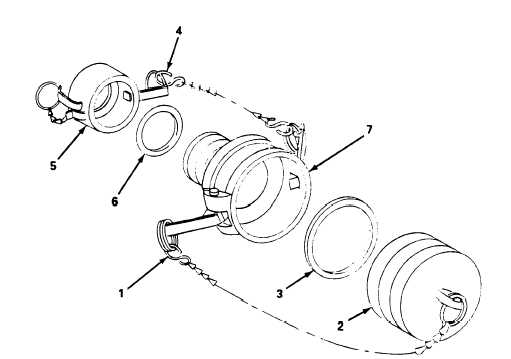
4-16. Adapter Assembly (cont). Figure  4-8.  Adapter  Assembly,  Disassembly/Assembly.
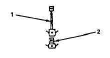
 b. Replace  (figure  4-9) (1)   Removal. (a) Pull upon suction hose assembly (1) camlock levers and remove suction hose. (b) Pull upon adapter camlock levers and remove adapter assembly (2) from fuel source. (2)  Installation. (a)  Position  adapter  assembly  (2)  on  fuel  source  and  secure  by  pushing  down  on  camlock  levers. (b)  Install  suction  hose  assembly  (1)  and  secure  by  pushing  down  on  camlock  levers. Figure 4-9. Adapter Assembly, Removal/Installation. 4-24

Privacy Statement - Press Release - Copyright Information. - Contact Us - Support Integrated Publishing

Integrated Publishing, Inc. - A (SDVOSB) Service Disabled Veteran Owned Small Business