|
| |
TM 10-4930-229-12&P
CHAPTER 2
OPERATING INSTRUCTIONS
Page
OVERVIEW . . . . . . . . . . . . . . . . . . . . . . . . . . . . . . . . . . . . . . . . . . . . . . . . . . . . . . . . . ...2-1
Section I.
Description and Use of Operator Controls and lndicators . . . . . . . . . . . . . . . . . . . . . . . . . 2-1
Section II.
Preventive Maintenance Checks and Services (PMCS) . . . . . . . . . . . . . . . . . . . . . . . . . . 2-5
Section III
Operation Under Usual Conditions . . . . . . . . . . . . . . . . . . . . . . . . . . . . . . . . . . . . . . . ...2-9
Section IV.
Operation Under Unusual Conditions . . . . . . . . . . . . . . . . . . . . . . . . . . . . . . . . . . . . . ...2-15
OVERVIEW
This chapter includes information on assembling and preparing the FARE to perform the specific mission for which
the equipment is designed. This chapter also includes information on the controls and indicators, operating
instructions, and preventive maintenance checks and services.
Section I. DESCRIPTION AND USE OF OPERATOR CONTROLS AND INDICATORS
Paragraph
Page
2-1
Operator Controls and lndicators . . . . . . . . . . . . . . . . . . . . . . . . . . . . . . . . . . . . . . . . . ...2-1
2-2
Elbow Coupler Valve and Butterfly Valve Assembly Controls and Indicators . . . . . . . . . . 2-1
2-3
Filter/Separator Controls and lndicators . . . . . . . . . . . . . . . . . . . . . . . . . . . . . . . . . . . ...2-3
2-4
Pump/Engine and Closed Circuit Refueling Nozzle . . . . . . . . . . . . . . . . . . . . . . . . . . . . . . 2-5
2-1. Operator Controls and Indicators. Many of the controls and indicators used with the FARE are
located on the individual assemblies that make up the FARE system. The controls are described in the following
paragraphs:
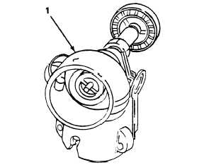
2-2. Elbow Coupler Valve and Butterfly Valve Assembly Controls and Indicators. (Refer to
figures 2-1 and 2-2.)
Figure 2-1. Elbow Coupler Valve Control.
2-1
|