Order this information in Print

Order this information on CD-ROM

Download in PDF Format


Click here to make tpub.com your Home Page

Page Title: Figure 1-2. Pump/Engine Assembly (Sheet 1 of 2).
Back | Up | Next

Click here for a printable version

Google


Web
www.tpub.com

Home


Information Categories
.... Administration
Advancement
Aerographer
Automotive
Aviation
Combat
Construction
Diving
Draftsman
Engineering
Electronics
Food and Cooking
Math
Medical
Music
Nuclear Fundamentals
Photography
Religion
USMC
   
Products
  Educational CD-ROM's
Printed Manuals
Downloadable Books


TM   10-4930-229-12&P a. Pump/Engine Assembly. (See figure  1-2.) 
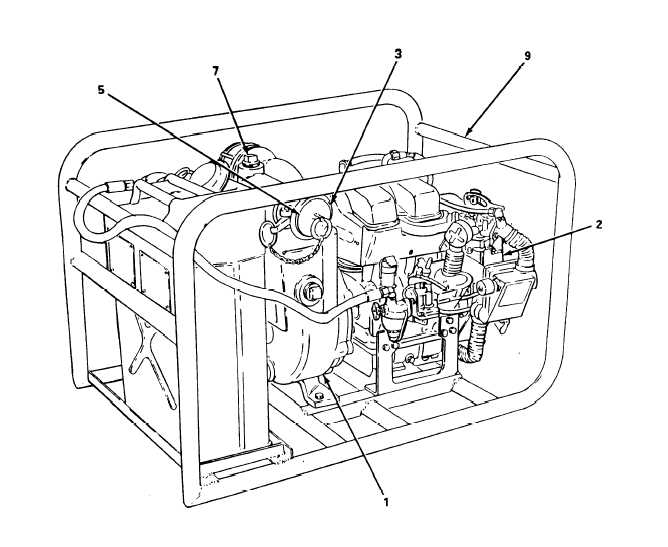
(1) The pump/engine assembly is a 100-gallon/minute (378.5-liter/minute) centrifugal pump (1 ) (refer to TM 10-4320-256-14&P for pump details). The pump is driven by a 4-cycle, 2-cylinder, 3-horsepower gasoline engine  (2). (2) The inlet connection to the pump is a standard 2-inch (5.08 cm) female camlock fitting (3). The discharge port is fitted with a 2-inch male camlock fitting (4). The inlet and outlet ports are provided with a dust plug (5) and cap  (6),  respectively. (3) A priming port  (7) is located on top of the pump housing and a drain plug (8) is located at the lowest point of the housing. Figure 1-2. Pump/Engine Assembly (Sheet 1 of 2). 1-4

Privacy Statement - Press Release - Copyright Information. - Contact Us - Support Integrated Publishing

Integrated Publishing, Inc. - A (SDVOSB) Service Disabled Veteran Owned Small Business