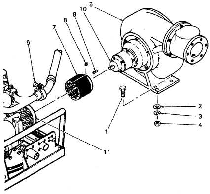
Order this information in Print

Order this information on CD-ROM

Download in PDF Format


Click here to make tpub.com your Home Page

Page Title: Figure 4-9. Fuel Transfer Pump Replacement
Back | Up | Next

Click here for a printable version

Google


Web
www.tpub.com

Home


Information Categories
.... Administration
Advancement
Aerographer
Automotive
Aviation
Combat
Construction
Diving
Draftsman
Engineering
Electronics
Food and Cooking
Math
Medical
Music
Nuclear Fundamentals
Photography
Religion
USMC
   
Products
  Educational CD-ROM's
Printed Manuals
Downloadable Books


TM 10-4320-351-14 (3) With  the  pump  fully  coupled  to  the  engine,  install  and  tighten  the  four  bolts  (1),  flat  washers  (2),  lock washers (3) and jam nuts (4) that secure the fuel transfer pump (5) to the module sub-frame. (4) Clamp exhaust line (6) to engine. (5) Install pumpage overtemperature sensor and test (para.  4.9.2.c). Figure 4-9.  Fuel Transfer Pump Replacement 4-23

Privacy Statement - Press Release - Copyright Information. - Contact Us - Support Integrated Publishing

Integrated Publishing, Inc. - A (SDVOSB) Service Disabled Veteran Owned Small Business