Order this information in Print

Order this information on CD-ROM

Download in PDF Format


Click here to make tpub.com your Home Page

Page Title: Figure 4-8. Flange Mounted Unisex Coupling Replacement
Back | Up | Next

Click here for a printable version

Google


Web
www.tpub.com

Home


Information Categories
.... Administration
Advancement
Aerographer
Automotive
Aviation
Combat
Construction
Diving
Draftsman
Engineering
Electronics
Food and Cooking
Math
Medical
Music
Nuclear Fundamentals
Photography
Religion
USMC
   
Products
  Educational CD-ROM's
Printed Manuals
Downloadable Books


TM 10-4320-351-14 (2) 
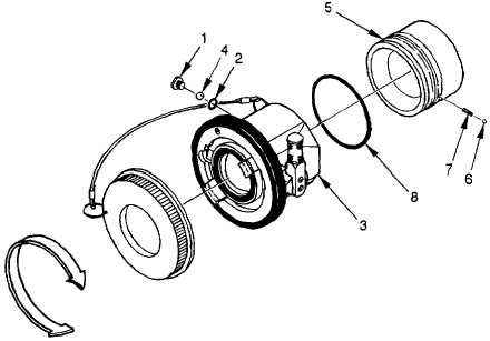
Start the unisex coupling (3) on to the inlet (5).  Install continuity ball (6) and spring (7) into hole in inlet (5) and hold in the compressed position while completing installation of unisex coupling (3) onto inlet (5). (3) Place a wiping rag beneath the unisex coupling (3).  Adjust  coupling  position  until  screw  hole  is  facing  up and ball race (rounded groove) in inlet is centered under screw hole.  Insert the balls (4) one at a time into the hole in the housing by rotating the unisex coupling (3) while installing the balls (4).  Once all 41 balls (4) are  installed,  place  O-ring  (2)  onto  ball  retaining  screw  (1)  and  install  the  ball  retaining  screw  (1).   Tighten retaining screw (1). Figure 4-8.  Flange Mounted Unisex Coupling Replacement 4-21

Privacy Statement - Press Release - Copyright Information. - Contact Us - Support Integrated Publishing

Integrated Publishing, Inc. - A (SDVOSB) Service Disabled Veteran Owned Small Business