|
| |
TM 10-4320-351-14
(1)
Connect the overtemperature sensor (1) wire leads to the multimeter leads.
(2)
Record whether or not the overtemperature sensor is closed, continuity; or open, no continuity.
(3)
If sensor is open, stop test and replace sensor. If sensor is closed, continue to step 4.
NOTE
The following steps must be done in the sequence shown.
(4)
Attach thermometer to the top edge, and inside, of the test container.
(5)
Attach the sensor to one end of the suspension wire and hook the other end over the edge of the test
container so that the sensor is close to, but not touching, the thermometer or the bottom of the container.
(6)
Fill the test container with water so that the sensor and at least 2 inches of the thermometer are covered.
(7)
Connect the sensor wire leads to the multimeter leads.
(8)
Plug the test container into a 1 10v outlet and observe temperature and multimeter until the sensor opens
and/or the water heats to +190F.
(9)
If sensor does not open, no continuity, stop test and replace sensor. If sensor opens, proceed to step 10.
(10)
Unplug the test container and let water cool to room temperature (less than +100F).
(11)
If sensor does not close, continuity, stop test and replace sensor. If sensor closed, proceed to step 12.
(12)
If the sensor opened (step 9) and closed (step 11), the sensor is acceptable.
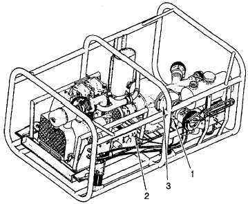
Figure 4-2. Pumpage Overtemperature Sensor Replacement
4.9.3 Replace Engine Air Filter Element. (Refer to figure 4-3.)
This task consists of:
a. Removal
b. Installation
INITIAL SET-UP:
Tools:
Materials/Parts Required:
No tools required
O-ring (Appendix I, Item 67)
Equipment Condition:
Pumping assembly shutdown (See para. 2.6)
a.
Removal.
(1)
Remove wing nut (1) and remove cover (2).
(2)
Remove wing nut (3) and slide filter element (4) out of filter body (5).
(3)
Remove and discard O-ring (6).
4-12
|