|
| |
TM 10-4320-351-14
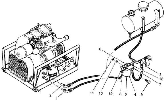
Figure 4-1. Fuel Filter Replacement
(7)
Remove the two bolts (9), flat washers (10) and self-locking nuts (11) that secure the engine fuel filter to the
module. Discard the self-locking nuts.
(8)
Remove the elbows (12) from the inlet and outlet of the engine fuel filter assembly. Dispose of the engine
fuel filter assembly in accordance with SOP.
b.
Installation.
(1)
Clean threads on elbows (12) as required, apply a light, even coat of sealing compound to threads and
install on engine fuel filter assembly.
(2)
Verify that drain valve (5) and vent valve (6) on engine fuel filter are closed.
(3)
Install fuel inlet and outlet line elbows (12) on engine fuel filter
(4)
Install engine fuel filter on module frame with two bolts (9), flat washers (10) and new self-locking nuts (11).
4-10
|