|
| |
TM 104320-351-14
j.
Install new head gasket (4) on cylinder and install cylinder head.
k.
Install cylinder head (5) on cylinder. Ensure pushrods are aligned with rocker arms (6) and pushrod pipes are
aligned with cylinder head.
1.
Install cylinder head nuts (7) and washers (8) finger tight, with lifting eye studnut in same location as observed
during removal.
Refer to figure 6-40.
m.
Place a straight edge (1) across intake and exhaust ports to align the cylinder heads. Use a 13 mm socket to
snug the cylinder head nuts (2).
n.
Gradually torque the head nuts in an alternating diagonal pattern. to 15 ft. lbs. (21.8 Nm), then to 23 ft. lbs.
(33.5 Nm) and finally to 30 ft. lbs. (43.7 Nm).
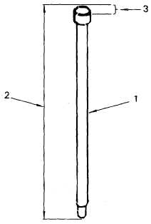
Figure 6-37. Pushrod Measurement
6-61
|