|
| |
TM 10-4320-351-14
1.11.3 System Electrical. (Refer to figure 1-7.)
All electrical power distribution, control and monitoring is performed by the electrical system. The system consists of the
system battery; the control panel; the alternator; the voltage regulator; the engine starting motor; the auxiliary pump;
various engine and pumpage sensors and controls; and the interconnecting cables. All electrical components except the
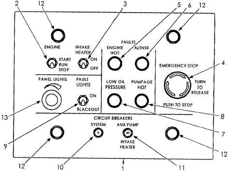
battery and the auxiliary pump are controlled or monitored by the control panel (1).
The ENGINE START-RUN-STOP (2) switch operates the starter to start the diesel engine and shuts off the fuel supply to
stop the diesel engine. The INTAKE HEATER switch (3) supplies power to the intake heater on the diesel engine to make
starting easier in cold weather. The EMERGENCY STOP switch (4) shuts off the fuel supply to the diesel engine when
pushed in. Four fault lights provide indication of a problem in the system:
The ENGINE HOT indicator (5) lights if the engine oil becomes too hot for normal operation.
The ALTNTR indicator (6) lights if the alternator voltage drops to less than the battery voltage.
The LOW OIL PRESSURE indicator (7) lights if the engine oil pressure drops too low for normal
operation.
The PUMPAGE HOT indicator (8) lights if the system pumpage becomes too hot for safety. A separate
circuit stops the engine.
The FAULT LIGHTS switch (9) allows the operator to disable the fault indicators during a blackout. A 5 amp circuit
breaker (10) opens and removes all electrical power from the pumping assembly if a malfunction or overload causes
power usage to exceed five amps. A 30 amp circuit breaker (11) protects the intake heater and auxiliary pump, if used.
Four panel lights (12) provide illumination for night operations. The PANEL LIGHTS dimmer control (13) allows the
operator to control the brightness of the panel lights.
Figure 1-7. Control Panel
1-12
|