|
| |
TM 10-4320-351-14
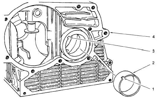
Refer to figure 6-23.
NOTE
The notch (1) on rear crankshaft bearing (2) must be aligned with matching notch
(3) on crankcase (4) during installation.
g.
Using bushing extractor tool, carefully install front crankshaft bearing (2) into flywheel end of crankcase (4).
Figure 6-23. Front Crankshaft Bearing Installation
Refer to figure 6-22.
h.
Install crankshaft (3) in crankcase using center bearing mounting tool to match hole in crankcase with hole in
center bearing support. Install center bearing support retaining screws (5) and flat washers (6).
i.
Torque center bearing support retaining screws (5) to 190 to 195 in. lbs. (21-23 Nm).
j.
Install rear crankshaft support in accordance with paragraph 6.4.2.
k.
Insert a 0.006 in. (0. 15 mm) thickness gauge between crankshaft (3) and crankcase. Place a screwdriver
between the crankcase center bearing support web and crankshaft throw to force crankshaft toward rear of
crankcase.
WARNING
Hot metal can burn and cause severe personal injury. Wear protective gloves.
I.
Using a warming oven, heat crankshaft gear (7) to 356°F - 392°F (180°C - 200°C) for 20 to 30 minutes.
6-38
|