|
| |
TM 10-4320-351-14
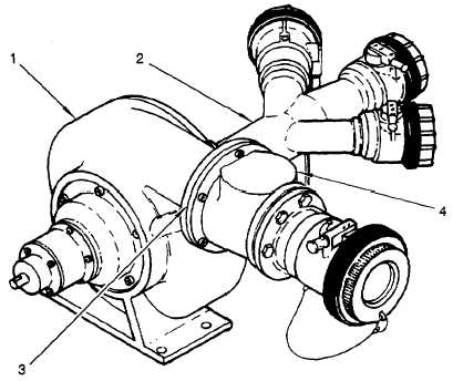
1.11.2 Fuel Transfer Pump. (Refer to figure 1-6.)
The fuel transfer pump (1) is a centrifugal pump with a precision ground impeller. A positive displacement, rotary vane
pump on the same shaft serves as a priming pump for the main impeller. This allows the pump to be started with a dry
system. Fuel is drawn from the fuel drums through suction hoses into a three-way inlet manifold (2). The convergence of
the three streams of fuel creates a swirling motion in the body of the manifold which, if not corrected, would cause a heavy
load on the pump. To correct this situation, three equally spaced fins in the manifold outlet straighten the flow, reducing
pump loading and increasing efficiency. The inlet manifold empties directly into the main impeller cavity of the fuel
transfer pump which discharges the pumpage through a discharge housing (4) to the filtration module. A flapper check
valve (3) in the discharge housing (4) prevents back flow to the fuel transfer pump.
The priming pump draws a suction on the fuel transfer pump inlet and discharges through a small outlet below the check
valve. The check valve is closed until the main impeller forces it open with pumpage flow. As long as the check valve is
closed, the priming pump continues to draw a suction. When the pumpage flow opens the check valve, pressure
equalizes across the priming pump and it loses suction. If pumpage flow is interrupted, the check valve closes and the
priming pump again draws a suction. If the system is flooded by gravity before starting, the priming pump has no effect.
The pump is designed to be operated at a constant speed of 3,600 rpm but can operate continuously at any lower speed
as long as the graphite journal bearings are lubricated. The pump can operate dry for periods of up to fifteen minutes
without lubrication. However, the pump should not be operated partially wet. If the pump has been running wet and the
inlet is depleted or closed, some pumpage will remain in the pump. The amount remaining will be sufficient to load the
impeller but not sufficient for pressurized lubrication of the bearings. Under this condition, the bearings will overheat and
seize, or deteriorate rapidly.
Figure 1-6. Fuel Transfer Pump
1-11
|