|
| |
TM 10-4320-351-14
Section III. PRINCIPLES OF OPERATION
1-11 GENERAL FUNCTIONAL DESCRIPTION.
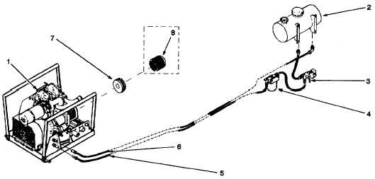
1.11.1 System Power. (Refer to figure 1-5.)
The diesel engine (1), fuel tank (2), fuel selector valve (3), fuel filter (4), and fuel supply line (5) and fuel return line (6)
comprise the pumping assembly power system. A splined flexible coupling adapter (7) on the diesel engine output shaft
mates with a flexible coupling (8) on the input shaft of the fuel transfer pump to move the pumpage.
The diesel is a compression ignition engine: ignition is achieved by compressing a fuel-air mixture in a cylinder until the
heat generated by compression causes the mixture to ignite. The resulting combustion causes the mixture to expand,
forcing the piston to move. The diesel engine is a two cylinder, direct injection engine. An individual fuel injector and
injection pump supplies pressurized fuel alternately to each cylinder. The engine is set to run at 3400 rpm, the optimum
speed for the fuel transfer pump to provide a 225 gpm (852 Ipm) flow. A flyweight governor operates from the camshaft to
maintain engine speed constant.
An on board fuel tank is the normal fuel source for engine operation. However, a fuel selector valve allows selection of an
external fuel source, if desired. JP-4, JP-5 or JP-8 jet fuel may be used. A fuel filter/water coalescer in the supply line
removes impurities and water from the fuel, regardless of the source. The engine fuel pump continuously supplies fuel to
the fuel injection pumps; a fuel return line allows surplus fuel to return to the fuel tank.
Figure 1-5. Power Subsystem
1-10
|