|
| |
TM 10-4320-351-14
5.7.7 Replace Relay K1. (Refer to figure 5-16.)
This task consists of:
a. Removal
b. Installation
INITIAL SET-UP:
Tools:
Materials/Parts Required:
Screwdriver, Cross Tip, #2
Nut, Self-Locking (Appendix I, Item 43)
(Appendix B, Section III, Item 3)
Combination Wrench, 1/4"
(Appendix B, Section III, Item 3)
Equipment Condition:
Combination Wrench, 3/16"
Accessory module removed from system.
(Appendix B, Section III, Item 3)
(para. 2.9)
a.
Removal.
(1)
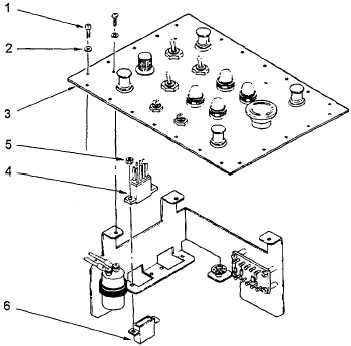
Remove twenty-four screws (1) and flat washers (2) that secure the control panel (3) to the control box.
(2)
Lift the control panel (3) from the control box and set on edge convenient to relay K1 (4).
(3)
Remove the two self-locking nuts (5) and remove the K1 relay (4). Discard the self-locking nuts (5).
b.
Installation.
(1)
Install relay K1 (4) in socket (6) with two self-locking nuts (5). (Relay is keyed to fit one way only.)
(2)
Install control panel (3) in control box with twenty-four screws (1) and flat washers (2).
Figure 5-16. Relay K1 Replacement
5-39
|