|
| |
TM 10-4320-351-14
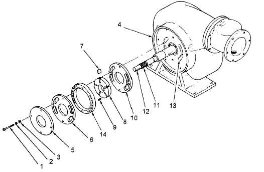
Figure 5-6. Rotary Vane Pump Repair
c.
Installation.
(1)
Set pump on base.
(2)
Place vane pump inner side plate (10) over shaft with outside face towards the impeller. (The inside face
has grooves connecting the inlet/outlet ports.)
(3)
Rotate impeller-shaft assembly (11) to place vane pump rotor key way (12) at top of shaft.
(4)
Place rotor key (9) in key way (12).
(5)
Hold impeller shaft (11) and slide vane pump rotor (8) over shaft and key (9).
(6)
Lay fuel transfer pump on inlet side and align inner side plate (10) mounting holes and fuel inlet/outlet ports
(13).
(7)
Place cam ring (14) over rotor (8) so that mounting holes are aligned, and the sixteen flow holes are aligned
with the corresponding inlet/outlet ports in the inner side plate (10).
(8)
Carefully place a carbon vane (7) in each of the five slots in the rotor (8). New vanes will be square on both
ends and may be installed without regard for direction. Vanes that have been run in will have worn shorter
in the direction of rotation. Install used vanes so that short side leads in the clockwise direction of rotation.
5-16
|