|
| |
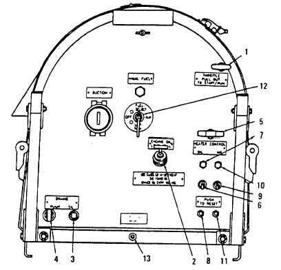
TM 10-4320-348-14
Figure 2-2. Operator’s View of External Controls and Indicators.
Key
External Control or Indicator (See Figure 2-2)
Function
1
Speed control
Controls engine speed. When positioned in the START position (fully
outward), the engine operates at highest speed. By moving lever between
START (fully outward) and STOP (fully inward) positions, the desired
operating speed can be obtained.
2
Oil dipstick/filler port
Indicates lube oil level in crankcase. Filler port for oil fill/change and adding
oil.
3
Lube oil drain plug
Provides external fitting to allow draining engine lube oil.
4
Pump fluid drain cock
Provides external fitting to allow draining pump fluid.
5
Recoil starter
Recoil starting handle and pull rope with automatic recoil for starting engine.
6
Heater control - oil
Two-position [ON (up)/OFF (down)] switch for controlling operation of
crankcase oil heater element.
7
Indicator lamp
Illuminated when oil heater control switch (6) is in the ON (up) position.
8
Circuit breaker
In the event of an overloaded circuit, push the button to reset the oil heater
circuit.
2-3
|