|
| |
TM 10-4320-348-14
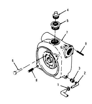
Figure 5-4. Pump Casing Assembly
(3)Blow out suspicious looking and difficult to reach areas with compressed air to remove deposits and reveal flaws.
(4)Inspect threaded studs (8 and 9) for damaged threads.
c. Repair.
(1)Remove and replace stud (8) or (9) from bolt hole if damaged.
(2)Pry the last thread of insert into center of hole with hook pick and remove insert.
(3)Install new insert to a depth of 0.25 to 0.5 pitch below the top surface of the tapped hole in pump casing (7).
(4)Remove drive tang with flat punch.
d. Installation.
(1)Position pump casing to engine and install four new self-sealing screws with seals (6). Tighten in an alternating
pattern. Torque to 32-35 ft-lb (4.43-4.84 m-kg).
(2)Install bushing (5) and pipe plug (4).
(3)Install bushing adapter (3), elbow (2), and hose clamp (1) and hose.
5-10
|