|
| |
TM 10-4320-343-14
f.
Close Control Panel as follows:
(1)
Press in on end of quick release pin and remove quick release pin from brackets at top of Control Panel
and Cover.
(2)
Lower Control Panel cover.
(3)
Turn the two fasteners on the Control Panel clockwise until the fasteners engage.
2.6 DECALS AND INSTRUCTION PLATES.
Figure 2-8 provides the location and identification of decals and instruction plates located on the 350 GPM Pumping
Assembly.
2.7 PREPARATION FOR MOVEMENT.
The 350 GPM Pumping Assembly can be moved either short distance around a worksite or long distance to another
location. The following paragraphs provide information to prepare the 350 GPM Pumping Assembly for movement.
2.7.1 Preparation for Movement at Worksite. Perform the following to move 350 GPM Pumping Assembly to another
location at a worksite.
a.
If operating, shutdown procedures in paragraph 2.5.1.2 for non-regulated models and paragraph 2.5.2.2 for
regulated models.
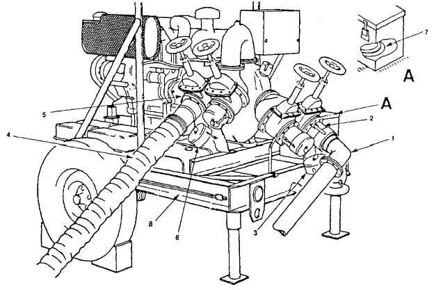
Figure 2-9. Disconnecting Suction and Discharge Hoses.
Change 1 2-29
|