|
| |
TM 10-4320-343-14
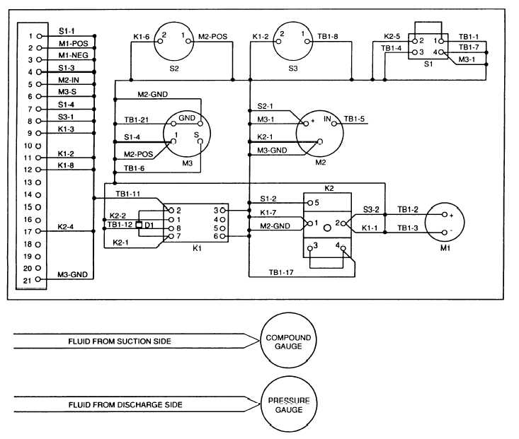
Figure 1-9.
Control Panel Assembly Functional Diagram.
1.14.2.6 Control Panel Assembly.
The control panel assembly provides the control and
indicators required for operation.
Figure 1-9 provides a functional block diagram
of the control panel.
The control panel receives and sends electrical signals to
and from the engine.
In addition, the control panel monitors the suction and
discharge pressures of the pump assembly.
1.14.2.6.1 Electrical and Control Signals.
The control panel provides most of the
physical components of the starting system.
Only the V-belt switch, oil pressure
switch, starter and alternator are not part of the control panel.
In addition, the
engine sends an electrical signal to an oil pressure gauge to indicate engine oil
pressure.
The engine also sends a tachometer signal to a tachometer located on the
control panel to indicate the engine speed.
An ampere meter monitors output of the
alternator.
1-20
|