|
| |
TM 10-4320-343-14
After the intake stroke, the compression stroke begins.
The piston is moved upward
by the crankshaft.
The push rod controlled by the camshaft causes the intake valve
to close.
Air in the cylinder’s combustion chamber is compressed.
When air is
compressed, heat is generated.
When the piston reaches the uppermost position, it
is at top dead center (TDC) and the air is completely compressed.
During the compression stroke, fuel is injected into the cylinder’s combustion
chamber.
Since the temperature is sufficient to ignite fuel, combustion takes
places and the power stroke begins.
Combustion causes expansion of the air and
fuel which increases the pressure,
Increased pressure forces the piston downward
causing the crankshaft to rotate.
Since the amount of fuel injected to the
combustion chamber is controlled, the speed of crankshaft rotation is controlled.
When the amount of fuel is increased, the speed of the engine is increased.
When the power stroke moves the piston to its BDC,
the exhaust valve is fully open.
When the piston starts to move upward, the exhaust stroke begins.
Pressure in the
combustion chamber and movement of piston force exhaust gases out of the combustion
chamber.
At the end of exhaust stroke, the exhaust valve is closed and
the intake valve is again open.
The piston is at TDC and next cycle begins.
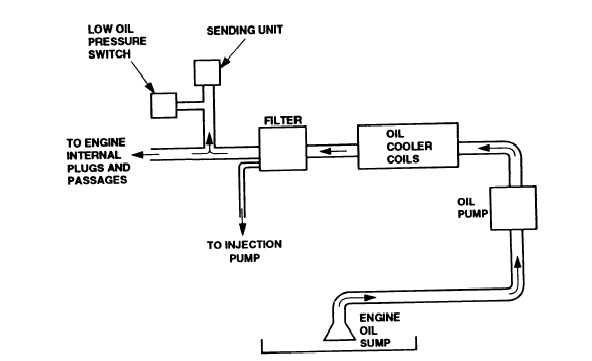
Figure 1-8.
Lubrication System Functional Diagram.
1.14.2.5.2 Lubrication System.
The lubrication system (figure 1-8) provides lubrication
and cooing to the engines parts.
The oil sump has an 8.5 quart (8.04 liter)
capacity and is filled with oil.
The oil pump is a gear type element driven by a
gear in the engines front cover.
When the engine is operating, a gear drives the
oil pump and oil is pumped from the oil sump to the oil cooler.
The oil cooler is
a coil cooled by the cooling fan.
The cooling fan causes oil to cool to a lower
temperature.
Oil is then pumped into the oil filter which is a throw-away element.
Contaminants are removed from the oil and the oil is pumped to the engine metering
plugs .
Metering plugs are oil jets within the engine block that spray oil on to
internal parts of the engine.
Oil is also pumped to the injection pump lube
supply .
The fuel injection pump lube supply is a line on the side of the oil
1-18
|