|
| |
TM 10-4320-343-14
1.14.2.4
Fuel System.
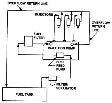
The fuel system is connected to the fuel tank and provides fuel to the engine. Figure 1-5 provides a functional diagram for
the fuel system. When the engine is cranked or operating, the fuel injection pump draws fuel through the filter/separator
that filters solid contaminants larger than one micron in size from the fuel. In addition, filter/separator removes water from
the fuel. After the filter/separator, fuel is drawn to the fuel feed pump The fuel feed pump is a diaphragm type pump
actuated by a cam in the fuel injection pump. When activated, the fuel feed pump provides a positive head of pressure '
to the fuel injection pump via a fuel filter. The fuel filter provides additional filtering of the fuel before it enters the fuel
injector pump. The fuel injection pump is a high pressure fuel delivery pump driven by a timing gear in the engine. The
main shaft in the injection pump has cams which operate plungers. Plungers pump fuel into the injector nozzles. The
amount of fuel injected into the nozzles can be controlled either mechanically (without regulator) or electrically (with
regulator) The fuel injector nozzles are single inlet, four outlet, high pressure injectors. High pressure injectors spray fuel
directly into the engine cylinders. Overflow lines are provided to carry excess fuel that is not needed for combustion. The
excess fuel is carried to the fuel tank and injection pump. Fuel is returned to the fuel tank by way of an overflow return
fitting on the fuel tank.
Figure 1-5. Fuel System Functional Diagram.
1-14.4 Change 1
|