|
| |
TM 10-4320-343-14
4.13.8 Safety Relay (K1) Base Replacement.
This task covers:
4.13.8.1 Removal
4 .
13 . 8 . 2 I n s t a l l a t i on
INITIAL SETUP
Tools
Equipment Conditions (continued)
General Mechanic’s Tool Kit (appendix B,
Control Panel Assembly Cover removed,
Section III, Item 1)
paragraph 4.13.1.
Materials/Parts
General Safety Instructions
Tags (appendix E, Section II, Item 12)
To prevent rolling or sliding, do not
work on equipment that is not securely
Equipment Conditions
s t a b i l i z e d.
Equipment shut down, refer to
Do not work on equipment without
paragraph 2.5.1.2 or 2.5.2.2.
following standard shop safety
precautions.
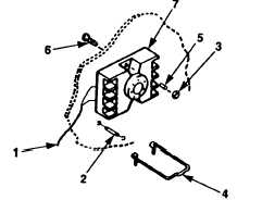
Figure 4-48.
Safety Relay (K1) Base
4.13.8.1 Removal.
Replacement.
To prevent rolling or sliding, do not work on equipment that is not
s e c u r e l y s t a b i l i z e d.
Ensure both wheels are secure.
Failure to obey this
warning-may result
a.
Tag wires (figure 4-48,
b.
Remove terminal screws,
in serious personal injury.
1) and diode (2) on terminals 2 and 7.
wires (1) and diode (2) from terminals 2 and 7.
Keep diode in safe place.
c .
Tag and disconnect remaining wires (l).
d .
Remove two nuts (3) retaining clip (4), spacers (5), screws (6) and base (7).
4.13.8.2 Installation.
a .
Install base (7),
b .
Connect wires (1)
c .
Connect wires (1)
screws (6), spacers (5), retaining clip (4) and nuts (3).
removed in step c of removal and remove tags.
and install diode (2) to terminals (2 and 7).
4-91
NOTE
|