|
| |
TM 10-4320-343-14
4.13.5 Oil Pressure (M1), Ammeter (M2), and Tachometer/Hourmter (M3) Replacemet.
This task covers:
4.13.5.1 Removal
4 .
13 . 5 . 2 I n s t a l l a t i on
INITIAL SETUP
Tools
Equipment Conditions (continued)
General Mechanic’s Tool Kit (appendix B,
Control Panel Assembly Cover removed,
Section III, Item 1)
paragraph 4.13.1.
Materials/Parts
General Safety Instructions
Tags (appendix E, Section II, Item 12)
To prevent rolling or sliding, do not
Equipment Conditions
work on equipment that is not securely
s t a b i l i z e d.
Equipment shut down, refer to
paragraph 2.5.1.2 or 2.5.2.2.
Do not work on equipment without
following standard shop safety
precautions.
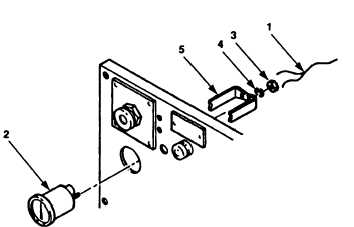
Figure 4-45.
Oil Pressure,
4.13.5.1 Removal.
Ammeter, and Tachometer/Hourmeter Replacement.
To prevent rolling or sliding, do not work on equipment that is not
s e c u r e l y s t a b i l i z e d.
Ensure both wheels are secure.
Failure to obey this
warning may result in serious personal injury.
a.
Tag and disconnect wires (figure 4-45, 1) from gauge (2).
b.
Remove two nuts (3), lockwashers (4), and retaining bracket (5) from gauge at
back of control panel.
c .
Remove gauge (2) from front of control panel.
4.13.5.2 Installation.
a.
Install gauge (2) through front of control panel.
b.
Install retainer bracket (5) and lockwashers (4) on gauge at back of control
panel.
4-87
|