|
| |
TM 10-4320-343-14
(2) Disconnect 12 V dc and measure for open circuit between K1 contacts 1/3 and 6/8.
a.
Relay K2.
(1) Apply positive 12 V dc to contacts 1 and 2 (ground) and meassure for continuity between K2 contacts 3/5 and
4/6.
(2) Disconnect 12 V dc and measure for open circuit between K2 contacts 3/5 and 4/6
b.
Switch (Rheostat) R2.
(1) Measure for open circuit between contacts 1 and 2 when switch is turned to the off position (fully
counterclockwise).
(2) Turn switch on (clockwise) and attach multimeter leads to contacts 1 and 2. Note that resistance increases
from 0 to 100 Ohms as switch knob is turned from off to fully on position.
c.
Panel Lights (DS I through DS 5).
(1) Briefly touch a 12 Vdc source to terminal of each light assembly at rheostat contact R2(1). All lamps should
illuminate.
d.
As required, start system and check that pressure gauges, ammeter and hourmeter/tachometer operate correctly.
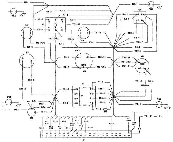
Figure 4-42.1 Control Panel Wiring Diagram (Model 350 PAFN).
Change 1 4-83
|