|
| |
TM 10-4320-343-14
4.10.18.1.3
Installation.
a.
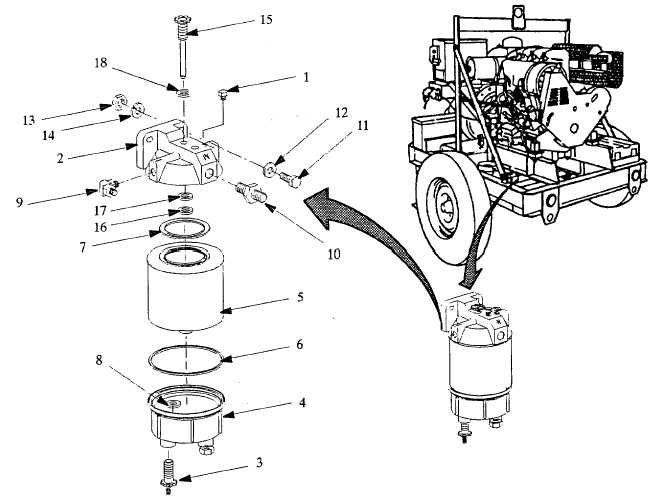
Lubricate the shaft on primer pump assembly (15) and screw (finger tight only) into head assembly (2).
b.
Install seal (18) and Invert head assembly (2) then place ring support (17) and plunger (16) onto shaft of primer
pump assembly (15) with cup facing upwards.
c.
Install head assembly (2) onto frame with screws (11), flat washers (12), nuts (13) and lockwashers (14).
d.
Install elbow (9) and adapator (10) into head assembly (2).
e.
Lubricate threads on drain knob (3) and screw (finger tight only) into bowl (4) then insert seal (8) on drain knob.
f.
Apply a coating of clean fuel or grease to the new o-ring (6) and seal (7) on filter element (5).
g.
Spin bowl (4) onto new filter element (5) then spin both onto the head assembly (2) snugly by hand only.
h.
Loosen vent plug (1) and operate the primer pump assembly (15) until fuel purges at the vent plug. Close the
vent plug, start the engine and check for leaks.
Figure 4-28.1 Fuel Filter (Water Separator) Servicing/Maintenance(Model 350 PAFN).
Change 1 4-55
|