|
| |
TM 10-4320-342-24
Section V. UNIT TROUBLESHOOTING
2-8. INTRODUCTION.
The troubleshooting table lists the common malfunctions you may find during the operation of the pump assemblies. You
should perform the tests, inspections and corrective actions in the order in which they appear in the table.
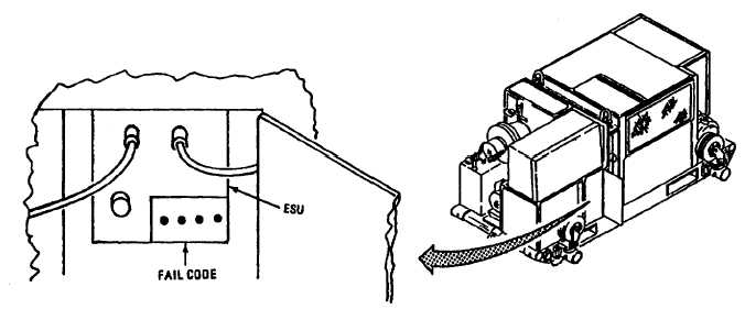
2-9. ENGINE FAULT INDICATORS.
Engine operation and fault indicators are positioned on the ESU front panel. They indicate the operational status of the
engine. The status is indicated by a Built-In Test Equipment (BITE) code made up of four indicators which indicate either
white or black as illustrated.
The ESU only displays the failure of a circuit; i.e., Fuel Torque Motor Fail. This means that indicated failure could be the
torque motor in the fuel control assembly, or in the wiring between the ESU and the torque motor. The troubleshooting
table takes this into consideration and gives you the additional checks that must be made to isolate the fault to a specific
component.
Figure 2-2. Engine Fault Indicators (Sheet 1 of 2)
2-13
|