|
| |
TM 10-4320-342-24
4-4. STARTER-GENERATOR REPAIR - continued.
Refer to Figure 4-4.
(7)
Inspect baffle discs (17 and 20) for dents, wear or other damage. Replace if defective.
(8)
Inspect bearing retainer (23) for dents, wear or other defects. Replace if defective. Refer to Figure 4-6.
(9)
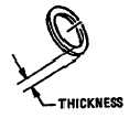
Inspect friction ring (1) as follow:
(a)
Inspect friction ring (1) for scored or oil soaked. Replace if scored or oil soaked.
(b)
Measure thickness of friction ring (1). Replace if thickness is less than 0.060 inch.
Figure 4-6. Friction Ring Measurement
Refer to Figure 4-7.
(10)
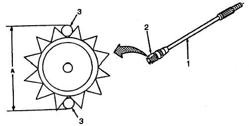
Inspect drive shaft as follows:
(a)
Inspect drive shaft (1) for cracks using magnetic particle inspection per MIL-I-6868.
(b)
Measure large spline (2) dimension A, on drive shaft (1) by installing two 0.1094 inch diameter pins (3) in
large spline. Replace shaft if dimension is less than 0.757.
Figure 4-7. Drive Shaft Measurement
4-12
|