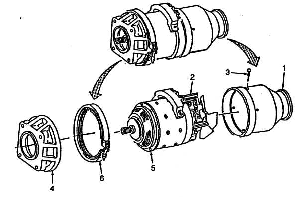
Order this information in Print

Order this information on CD-ROM

Download in PDF Format


Click here to make tpub.com your Home Page

Page Title: Figure 3-38. Air Inlet and Adapter Installation
Back | Up | Next

Click here for a printable version

Google


Web
www.tpub.com

Home


Information Categories
.... Administration
Advancement
Aerographer
Automotive
Aviation
Combat
Construction
Diving
Draftsman
Engineering
Electronics
Food and Cooking
Math
Medical
Music
Nuclear Fundamentals
Photography
Religion
USMC
   
Products
  Educational CD-ROM's
Printed Manuals
Downloadable Books


TM 10-4320-342-24 3-22.  STARTER-GENERATOR REPAIR - continued. Refer to Figure 3-38. (38) Position air inlet (1) on end bell assembly (2) and install screws (3). (39) Position adapter (4) on drive end bell (5) and secure with clamp (6). Figure 3-38.  Air Inlet and Adapter Installation 3-87

Privacy Statement - Press Release - Copyright Information. - Contact Us - Support Integrated Publishing

Integrated Publishing, Inc. - A (SDVOSB) Service Disabled Veteran Owned Small Business