|
| |
TM 10-4320-342-24
2-36. BLEED AIR SOLENOID VALVE ASSEMBLY REPLACEMENT - continued.
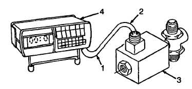
b. TEST. Refer to Figure 2-58.
(1)
Connect multimeter negative (Black) lead (1) to pin A and positive (Red) lead (2) to pin B on solenoid (3).
(2)
With leads (1 and 2) connected, check reading on multimeter (4) for 25-30 ohms. If multimeter indicates higher
than 30 ohms, replace solenoid (3).
Figure 2-58. Ohms Testing of Bleed Air Solenoid
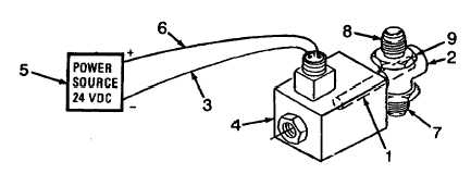
Refer to Figure 2-59.
(3)
If reading indicates 25-30 ohms, check for retraction of plunger (1) in body assembly (2).
(4)
Connect negative lead (3) to Pin A on solenoid (4) and negative of a 24 vdc power source (5).
(5)
Connect positive lead (6) to Pin B on solenoid (4) and to positive of a 24 vdc power source (5).
(6)
With leads (3 and 6) connected to solenoid (4) on 24 vdc power source (5), look through the tube connectors (7
and 8) on the valve body assembly (9). If light can be seen, the plunger (1) in the valve body assembly (9) has
retracted and valve body assembly is good. If not, replace valve body assembly (9).
Figure 2-59. Testing Plunger Retraction of Bleed Air Solenoid Valve
2-145
|