Order this information in Print

Order this information on CD-ROM

Download in PDF Format


Click here to make tpub.com your Home Page

Page Title: Figure 2-55. Primary Solenoid Valve Replacement
Back | Up | Next

Click here for a printable version

Google


Web
www.tpub.com

Home


Information Categories
.... Administration
Advancement
Aerographer
Automotive
Aviation
Combat
Construction
Diving
Draftsman
Engineering
Electronics
Food and Cooking
Math
Medical
Music
Nuclear Fundamentals
Photography
Religion
USMC
   
Products
  Educational CD-ROM's
Printed Manuals
Downloadable Books


TM 10-4320-342-24 
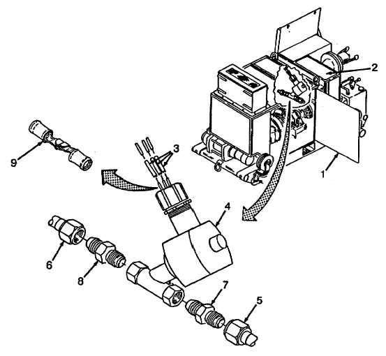
2-34.  PRIMING SOLENOID VALVE REPLACEMENT - continued. NOTE Wire    numbers    are    stamped    on    each    electrical    wire.        This    information,    in conjunction with data on FO-1 and FO-2 200/600 GPM Pump Wiring Diagram, may be used to connect wires if tags are lost or illegible. (5) Connect electrical wiring as tagged. (6) Slide sleeving insulation (3) over terminals (9) and shrink sleeving on wiring. (7) Close door (1) and install panel (2). Figure 2-55.  Primary Solenoid Valve Replacement 2-141

Privacy Statement - Press Release - Copyright Information. - Contact Us - Support Integrated Publishing

Integrated Publishing, Inc. - A (SDVOSB) Service Disabled Veteran Owned Small Business