|
| |
TM 10-4320-342-10
1-14. PRINCIPLES OF OPERATION - continued.
(3)
The turbine shaft is coupled to the engine gearbox which consists of various reduction gears. The main shaft
rotates and is coupled to an auxiliary speed reducer for proper pump speed. Other items attached to the
gearbox are the starter/generator and the fuel valve.
(4)
Engine is electrically controlled through a variety of sensors, the fuel control assembly and the fuel solenoid
valve. Engine protection is provided by an oil temperature switch, low oil pressure switch, a thermocouple
and an Electronic Sequencing Unit (ESU).
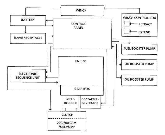
c.
Electrical System. Refer to Figure 1-2.
The diagram shows the electrical flow of components in the electrical system.
Figure 1-2. Electrical System Diagram
1-10
|