|
| |
TM 10-4320-324-14
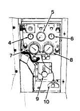
2-2. Controls and Indicators (CONT).
d.
Oil Pressure Gauge. The oil pressure gauge (4) indicates engine oil pressure by pounds per square inch (PSI). This
gauge is graduated in 10 pound increments from 0 to 80 PSI.
e.
Tachometer/Hourmeter. The tachometer/hourmeter (5) indicates engine speed in
revolutions per minute (RPM). This gauge is graduated in 100 RPM increments from 0
to 3000 RPM. The center portion of the gauge indicates the total number of hours the
engine has been operated.
f.
Ammeter Gauge. The ammeter gauge (6) indicates alternator amperage output. This
gauge is graduated in 30 amp increments from 0 to +60 AMPS and from 0 to -60 AMPS.
g.
Suction Gauge. This gauge (7) is marked SUCTION and indicates pump suction
pressure and vacuum per square inch (PSI). This gauge is graduated in one unit
increments from 0 to 30 PSI for both vacuum and pressure with numerals at five unit
intervals on the pressure side and at 10 unit intervals on the vacuum side.
h.
Discharge Gauge. This gauge (8) is marked DISCHARGE and indicates pump discharge
pressure in pounds per square inch (PSI). This gauge is graduated in 5 pound increments from 0 to 160 PSI with
numerals at 20 PSI intervals.
i.
Engine Throttle. The engine throttle (9) provides manual speed selection. Turning throttle control counterclockwise
increases engine speed. Clockwise rotation decreases engine speed.
j.
Handpump. The handpump (10) is used to pressurize the cold start reservoir. If the outside air temperature is below
+40
F (+5
C) the cold start system may be used to assist in starting engine.
Section II. PREVENTIVE MAINTENANCE CHECKS AND SERVICES
2-3. Introduction.
a.
General. Preventive maintenance checks and services are performed before, during, and after operating the equipment.
(1)
Before Operating. Review all CAUTIONS and WARNINGS applicable to the pumping assembly. Perform the
before (B) PMCS in accordance with Table 2-1.
(2)
While Operating. Pay special attention to any CAUTIONS and WARNINGS applicable to the pumping assembly.
Perform the during (D) PMCS in accordance with Table 2-1.
(3)
After Operating. Be sure to perform the after (A) PMCS in accordance with Table 2-1.
(4)
If equipment fails to operate refer to Table 3-1 and troubleshoot using proper equipment. Use the proper forms to
report any deficiencies, see DA PAM 735-750.
2-2
|