|
| |
TM 10-4320-324-14
1-22. Pumping System.
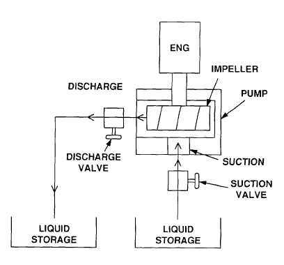
Figure 1-11. Pump System Functional Diagram
a.
Impeller Shaft. The impeller shaft is the direct link between the engine and pump. The faster the engine runs, the faster
the impeller shaft turns the impeller, raising pump pressure.
b.
Impeller. The impeller, powered by the engine, through the impeller shaft, uses centrifugal force to pull the liquid into the
pump housing through the suction valve and diverted it to the discharge valve.
c.
Suction Valve. The suction valve is a manually operated gate valve which provides pump flow shutoff. When opened,
the suction valve allows liquids to be brought through the centrifugal pump.
d.
Centrifugal Pump. The centrifugal pump uses energy provided by the engine to move fluids from one place to another.
e.
Discharge Valve. The discharge valve is a manually operated gate valve which provides pump flow shutoff. When
opened, the discharge valve allows liquid to be discharged through the centrifugal pump.
1-17/(1-18 blank)
|