|
| |
TM10-4320-316-14
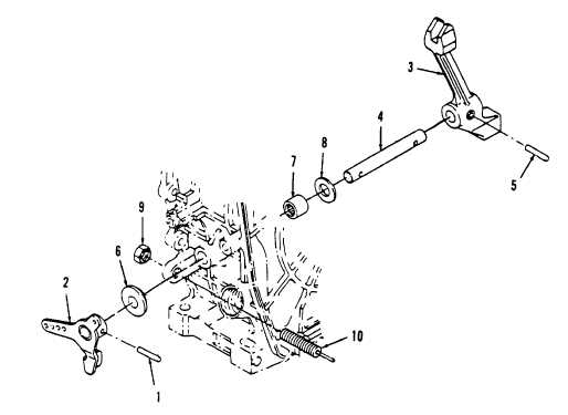
Figure 6-5. Governor Assembly Removal.
b. Inspection.
(1) Clean all parts with diesel fuel.
(2) Inspect all components for damage or excessive wear. Replace any components damaged or worn.
(3) Check that the outside diameter of the outer rotor is at least 1.138 inches (28.90 mm).
(4) Check that the crankcase cover housing inside diameter is less than 1.149 inches (29.18 mm).
(5) Check that the clearance between housing ID and outer rotor OD is between 0.005-0.011 inch (0.120-
0.280 mm).
(6) Check that outer rotor and inner rotor width is at least 0.311 inch (7.90 mm).
(7) Check that the crankcase cover housing depth is less than 0.319 inch (8.10 mm).
(8) Check that the clearance between the inner and outer rotor is less than 0.010 inch (0.25 mm).
6-13
|