|
| |
TM 10-4320-311-14
s.
Refer to Figure 4-16. From the outside of the sound enclosure front panel assembly, pull throttle cable (9) out of
the front panel.
t.
Pull recoil starter rope T-handle (10) until two feet of rope is exposed.
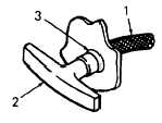
Figure 4-20. Recoil Starter Rope T-Handle
u.
Refer to Figure 4-20. Grasp rope (1) firmly and pull the knot six inches out of T-handle (2). Untie the knot in the
rope.
v.
Pull rope (1) through, and free of, T-handle (2) and front panel grommet (3).
w.
Push rope (1) through the hole in T-handle (2) and retie the knot.
x.
Allow the rope to rewind until T-handle (2) seats on the starter case.
y.
Refer to Figure 4-16. Remove the sound enclosure front panel assembly from frame (6).
INSPECTION: Refer to Figure 4-16.
a.
Inspect pump drain cock and fitting (4), oil drain plug and fitting (8), and oil dipstick and filler tube (5), for cracks,
damaged threads, leaks, or other damage.
b.
Inspect throttle cable (9) and recoil starter rope T-handle (10) for damage.
REPAIR:
Repair by replacing damaged components
INSPECTION' Refer to Figure 4-16.
a.
Inspect the riveted information plates on the sound enclosure front panel assembly. Damaged Information plates
must be removed and replaced. If any rivets are missing from undamaged information plates, the missing rivets
must be replaced.
b.
Inspect acoustical foam (11) within the sound enclosure front panel assembly. If acoustical foam blocks air flow,
or is torn, scarred, or shows signs of contacting the hot engine surface, it must be replaced.
REPAIR:
WARNING
Wear safety goggles during blind rivet removal to protect your eyes from flying metal chips.
a.
Drill out all rivets (12) until damaged information plate can be removed.
b.
Replace damaged information plate.
c.
Use hand blind riveter and M24243/1B403 rivets to attach new information plate.
4-38
|