|
| |
TM 10-4320-311-14
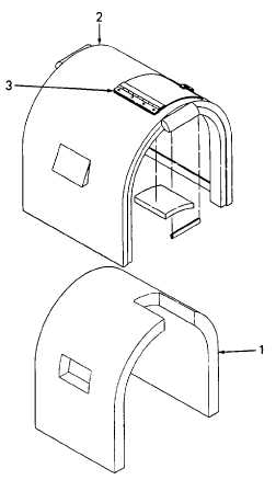
Figure 4-9. Sound Enclosure Cover Assembly
INSPECTION: Refer to Figure 4-9.
a.
Inspect the riveted components of the sound enclosure cover assembly. Damaged components must be
removed and replaced. If any rivets are missing from undamaged components, the missing rivets must be
replaced.
b.
Inspect the acoustical foam (1) within the sound enclosure cover assembly (2). If acoustical foam blocks air flow
or is torn, scarred, or shows sign of contacting a hot engine surface, it must be replaced.
REPAIR:
WARNING
Wear safety goggles during blind rivet removal to protect your eyes from flying metal chips.
a.
Drill out all rivets (3) securing the damaged component until component can be removed.
b.
Replace damaged component.
4-25
|