|
| |
TM 10-4320-311-14
6-8. Replace/Inspect Camshaft.
This task covers:
a.
Removal
b.
Inspection
c.
Installation
INITIAL SETUP
Tools
Equipment
Condition
Tool Kit, General Mechanics (Item 1,
Para
Appendix B, Section III)
5-14
Fuel injection pump removed
Micrometer Set (Item 3, Appendix B,
Section III)
6-5
Cylinder head and valve assembly
removed.
Arbor Press (Item 3, Appendix B,
Section III)
6-6
Crankcase cover removed.
Materials/Parts
Diesel fuel (Item 2, Appendix E,
Section II)
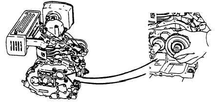
Figure 6-10. Removing the Camshaft
REMOVAL: Refer to Figure 6-10.
CAUTION
Keep exhaust and Intake tappets separate. They may fall down when pulling out the camshaft and
may be confused.
a.
Check the location of the timing marks on all gears.
b.
Lay engine down on the flywheel side to prevent tappets from falling out.
c.
Pull out the camshaft.
6-14
|