|
| |
TM 10-4320-311-14
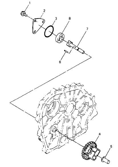
Figure 6-8. Lube Oil Pump Assembly
d.
Replace lube oil pump if the outer and inner rotor width is less than 0.311 inch (7.9 mm)
e.
Replace crankcase cover if the housing depth is greater than 0.319 inch (8.1 mm)
f.
Replace lube oil pump If the clearance between the inner and outer rotor Is less than 0.010 inch (0.25 mm).
INSTALLATION: Refer to Figure 6-9.
a.
Insert lubricating oil pump assembly (1) from the outside of the crankcase cover (2). Coat the rotor with oil
before installing the cover.
b.
Insert drive pin (3) into the lubricating oil pump shaft (4).
c.
Insert spindle (5) into the weights (6) on the governor gear assembly (7), then push the governor gear assembly
(7) onto the oil pump shaft (4). Ensure that gear is firmly engaged onto pin (3)
6-12
|