|
| |
TM 10-4320-307-10
2-1
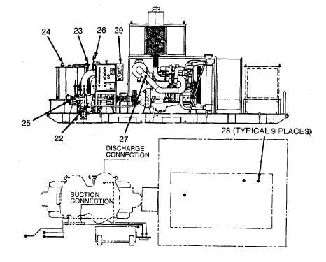
CONTROLS AND INDICATORS (CONT).
Table 2-1. Operator's Controls and Indicators (Cont)
Key
Control or Indicator
Function
22
Supply 3-way fuel valve
Allows operator to select the fuel supply from the pumping
assembly fuel tank (UNIT TANK position) or from an exteri-
or source (AUXILIARY position). There is also an OFF
position.
23
Return 3-way fuel valve
Allows operator to select a fuel return to the pumping as-
sembly. fuel tank (UNIT TANK position) or to an exterior
tank (AUXILIARY position). There is also an OFF position.
24
Fuel tank level gauge
Allows operator to check fuel quantity.
25
Pump oil sight gauges (bullseyes)
Allows operator to check pump oil level.
26
Pump vent valves
Allows operator to bleed air from pump during initial startup.
27
Air cleaner D/P indicator
Allows operator to check for a clogged inlet filter element.
28
Lamps and transducer isolation
Transducer measures key engine and pumping functions.
Valves. When specifications are exceeded or not met
transducer lamp indicates area of trouble and shuts down
pumping unit.
29
Discharge suction vent valves
Located in the back of gauges, allows operator to bleed air
from gauge piping prior to initial operation.
2-4
|