 |
|||
|
|
|||
|
Page Title:
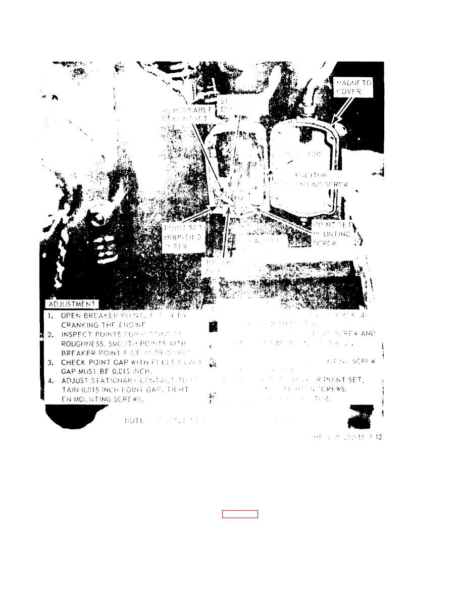
Figure 3-12. Magneto breaker point, replacement and adjustment. |
|
||
| ||||||||||
|
|
 TM 10-4320-202-15
Figure 3-12. Magneto breaker point, replacement and adjustment.
drive gear on the shaft so that it enganes the
d. Drive Gear. Remove the lockwire and
key on th impulse coupling with the timing
nut from the end of the magneto shaft and
mark on the gear at the 12 o'clock position.
remove the drive gear. To install, turn the
e. Installation. Install and time the magento
magneto rotor until the coupling pawl engages
( f i g . 3-13 and 3-14).
the stop pin in the flange, then position the
3-16
|
|
Privacy Statement - Press Release - Copyright Information. - Contact Us |
