 |
|||
|
|
|||
|
Page Title:
Governor linkage and Speed Control |
|
||
| ||||||||||
|
|
 TM 10-4320-202-15
3-29. Governor linkage and Speed Control
a. Adjustment. Adjust engine speed (fig. 3-
10). Engine speed with pump operating under
a load should be 2,800 50 rpm.
lution counter on starting pulley end of crankshaft,
when adjusting the governor, the correct adjustment
should be 2,950 rpm No Load or 2,800 rpm F u l l
Load
b. Removal. Remove the governor linkage
and speed control (fig. 310).
c. Disassembly. Disassemble speed control
d. Cleaning and Inspection.
(1) Clean all parts with approved dry
cleaning solvent and dry thoroughly with a
clean cloth or low pressure air.
(2) Inspect all parts for cracks, distortion,
wear at bearing points, or other damage. Re-
place damaged parts.
e. Reassembly. Reassemble the speed con-
trol (fig. 311).
f. Installation. Install the speed control as-
sembly and governor linkage (fig. 3-10).
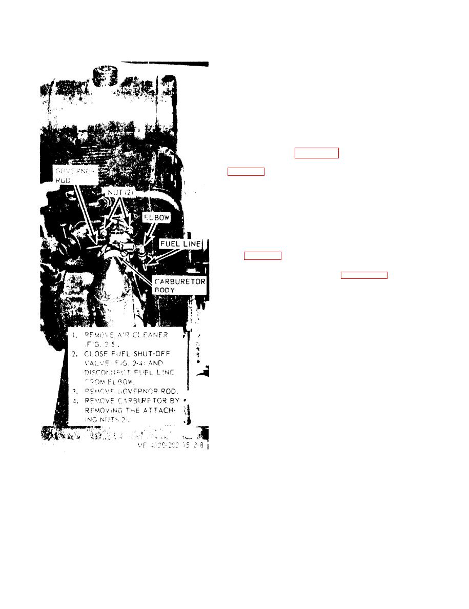
Figure 38. Carburetor, removal and installation.
3-12
|
|
Privacy Statement - Press Release - Copyright Information. - Contact Us |
