 |
|||
|
|
|||
|
|
|||
| ||||||||||
|
|
 TM 10-4220-202-15
roads, under all conditions of weather and
1-5. Identification and Tabulated Data
terrain.
a. Identitification. The Pumping Assembly
has three major identification plates. The in-
1-4. Components
formation contained on these plates is listed
a. Pump.
below.
(1) U.S. Plate. This plate is mounted
(1) Description of unit. The pump is a
on the top cover of the pumping assembly.
self-priming centrifugal, fuel dispensing pump.
It provides official nomenclature of the unit,
It is close-coupled to the engine by an inter-
model number, serial number, contract num-
m e d i a t e adapter the pump impeller being
ber, dimensions, cubage, weight, date inspected
mounted directly on the engine crankshaft. The
and date shipped.
suction inlet is provided with a swing check
valve to retain the liquid in the body of the
(2) Serial Number Plate. This plate is
pump when not in operation. The casing has
mounted on the pump-engine assembly. It pro-
a drain plug for completely emptying the
vides information regarding pump manufactur-
volute. There is a 1 1/2 inch priming plug
er, model number, serial number, Federal stock
for filling the separation chamber, volute and
number, type of drive and contract number.
s u c t i o n chamber to prime the pump. The
(3) Engine Plate. The engine plate is
suction inlet is on a horizontal position on the
mounted on the upper portion of the engine
side of the pump opposite the engine. The
shroud, on the pulley end of the engine. It
pump discharges through an opening in the
provides the model number, serial number,
top of the pump casing. Suction and discharge
size, rated speed, specification number, horse-
openings in the pump casing have 1 1/2 inch
power and manufacturing date. It also pro-
(International Pipe Standard) threads. The
vides engine operation and maintenance infor-
pump is coupled to the engine by an inter-
mation.
mediate casting, which incloses a mechanical
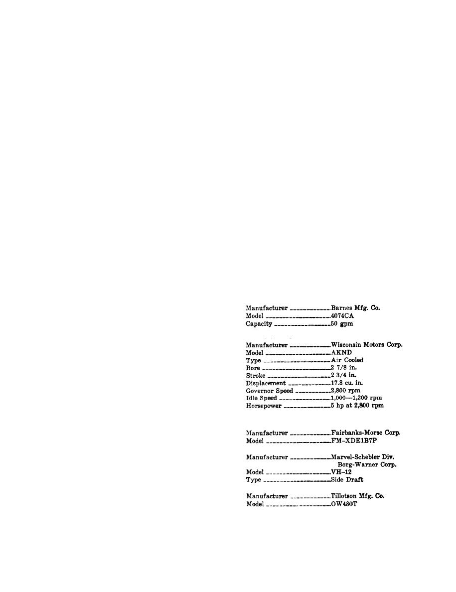
b. Tabulated Data.
seal on the crankshaft.
(1) Pumping assembly.
(2) Priming characteristics. The pump is
designed to prime in about 2 minutes when
the following conditions are present:
(2) Engine.
(a) A static suction lift of at least 5
feet.
(b) A 1 1/2 inch suction hose 50 feet
long.
(c) The impeller turning approximate-
ly 2,800 rpm. The pump is designed to deliver
n o t less than 22 pounds per square inch
pressure and not more than 27 psi at each
(3) Engine accessories.
nozzle discharge: provided two 50 foot lengths
(a) Magneto.
of 1 1/2 inch discharge hose are used in
parallel. Prevailing temperature of gasoline
being pumped should be between 50 and
(b) Carburetor.
60 F. When all the above conditions are pres-
ent, the pump should deliver 50 gpm.
b. Engine. The engine is a single cylinder,
air cooled, gasoline driven type capable of
(c) Fuel strainer.
d e v e l o p i n g about 5 horse power at 2,800
revolutions per minute (governed speed).
1-3
|
|
Privacy Statement - Press Release - Copyright Information. - Contact Us |
